
Introduction — a quick reality check
Have you ever stood over a workbench wondering why a motor that looks fine stalls under load? (It happens more than you think.) In many workshops the motor controller is the hidden bottleneck — the piece that decides whether a design hums smoothly or grinds to a stop. I call this out because motor controller choices change system efficiency, heat, and control precision in ways most teams don’t expect.
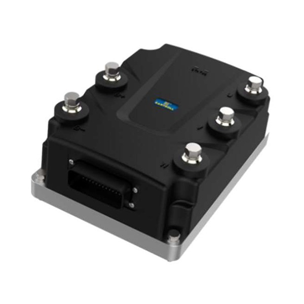
For a direct snapshot: a modest mismatch between controller torque control and motor characteristics can cut useful runtime by 10–30%. That’s lost productivity, extra heat, and frustrated technicians. I want to walk you through the practical side — how these devices work in real settings, what trips people up, and what to look for next. We’ll touch on PWM, inverter behavior, and power converters — short, helpful terms you’ll see again. Let’s move on to where traditional methods fail, and why that matters for your next build.
Hidden flaws in traditional motor controllers
Why do legacy designs fail?
When I dig into failing systems I often find the same culprit: an old-school bldc motor controller that wasn’t chosen with the full use-case in mind. Engineers assumed a simple drive would do. But real loads change. Sensorless commutation drifts at low speed. Field-oriented control needs precise current sensing. The result: poor torque at low RPM, noisy response, and surprising heat in the inverter and power converters. Look, it’s simpler than you think — mismatch equals trouble.
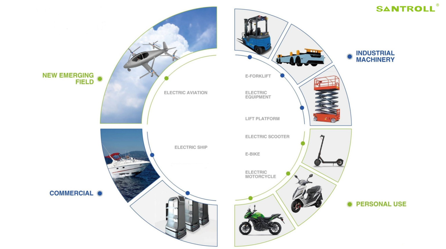
I’ve seen controllers that behave fine on test benches but fail on the factory floor. Why? Because controlled tests rarely replicate thermal cycles, mechanical shock, or noisy electrical environments. PWM schemes without adaptive filtering let spikes through, and control loops tuned for one motor won’t work for another. We fix this by demanding better telemetry, tighter current loops, and by testing with realistic loads. It takes time. But it saves hours of debugging later and — yes — a lot of warranty headaches.
New principles and what to test next
What’s the practical upgrade path?
Moving forward, I focus on three core ideas: adaptive control, robust sensing, and scalable power design. Modern ac electric motor controller designs fold these ideas into firmware and hardware. Adaptive control lets the drive adjust to motor changes on the fly. Robust sensing (better current shunts, improved encoder handling) reduces drift. Scalable power stages mean the controller can handle short surges without shutting down. I prefer equipment that gives clear telemetry — current, voltage, temperature — so we can trace faults fast.
In practice, evaluate controllers by running a case scenario: start with a low-speed torque test, then apply a step load, finally run a thermal cycle. Watch for oscillation in the control loop, watch for torque drop, and watch temperature rise. If telemetry is sparse, you’ll be blind. Also consider integration needs: does the controller expose CAN, SPI, or simple analog I/O? Those communications matter when you scale systems or use edge computing nodes to manage fleets. — funny how that works, right?
To wrap up, here are three concise evaluation metrics I always use when choosing a motor controller: measurable torque response (rise time and overshoot), thermal headroom under sustained loads, and fidelity of telemetry and diagnostics. Test results should be repeatable and documented. I trust parts that let me see what’s happening inside the control loop. In my experience, that visibility cuts field returns and speeds commissioning. For a practical partner and clearer specs, check Santroll — they publish useful data and solid hardware that I’ve relied on in field tests.