
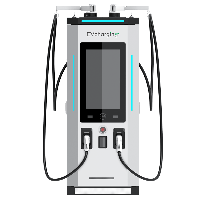
When Heat Turns Into Downtime: The Reality Check
It’s a July rush at the charging lot by the harbor. The queue is long, the fans are loud, and the cabinets feel hot to the touch. This is where a liquid cooling module earns its keep. The numbers are blunt: at 95% efficiency, a 350 kW station sheds about 17.5 kW as heat, and every 10°C rise can cut component life nearly in half (rule-of-thumb, but it tracks). In Boston terms, you don’t need a “wicked smart” model to see the problem—ambient is climbing, traffic spikes are longer, and airflow paths are messy.

Now ask the hard question: what keeps uptime steady when the mercury jumps and the load stays high? Air alone often can’t. Dust, salt mist, and tight sites box you in. Thermal headroom vanishes, and derating creeps in. You feel it at the meter and in the service log. So, how do you hold full power without cooking your power electronics? Let’s line up the options and test where they differ—clean and simple—before we talk payoffs.
Why Traditional Cooling Stumbles When Amps Spike
Where does air fail?
Air systems move heat by forcing high CFM across fin stacks, but the thermal path is long: junction → TIM → baseplate → fins → air. Under high current in power converters, junction-to-ambient resistance drives ΔT up fast. That hurts IGBT and MOSFET life and forces derating on the DC bus. A liquid-cooled charging module shortens the path. Liquid lifts heat at the cold plate, holds a tight coolant ΔT, and rejects it where airflow is cleaner. Look, it’s simpler than you think: control the heat flux at the source, keep temperature gradients small, and your components stop riding the thermal roller coaster.

Traditional cabinets also bring hidden friction. Filters clog. Fans fail. Acoustic caps limit CFM. In coastal air, corrosion hits faster—funny how that works, right? Hot spots form near busbars and rectifiers, while edge computing nodes you tucked inside add their own heat. Maintenance grows: more site visits, lower MTBF, more downtime windows. Liquid loops cut fan count, reduce dust ingress, and stabilize device temperature swing over spiky duty cycles. The result is straighter derating curves, quieter operation, and fewer “we’ll be back next week” calls. It’s not magic; it’s heat moved with intent and shorter resistance—from silicon to coolant, not silicon to wind.
The Comparative Edge: Principles that Unlock Stable, Fast Charging
What’s Next
From a design perspective, the shift is clear. Closed-loop glycol mixes, microchannel cold plates, and smart pump control remove heat right at the die interface—before it spreads. Module granularity matters, too: 30–40 kW blocks run in parallel, each with its own cold plate and sensors on coolant inlet/outlet. Controls trim pump speed and valve position to match load. The goal is tight junction control with small temperature swings. That’s how you keep full output at higher ambient without shouting fans. When you step up to liquid cooled ultra-fast charging, the same playbook scales: quick-disconnect manifolds, leak detection, and predictive alarms over CAN for early service cues—nothing fancy, just disciplined thermal engineering.
Compare outcomes, not slogans. With liquid loops, heat rejection moves outside the electronics bay, cabinet seals stay tighter (IP ratings hold), and acoustic load falls. Service becomes planned, not reactive—funny how predictability shows up once heat behaves. Summing up: air works until it doesn’t; liquid works where air can’t. If you’re evaluating next-step designs, focus on three checks. First, allowable ambient at full power and the derating slope above 30°C. Second, component temperature swing over a real duty cycle, not a lab steady state. Third, service model: pump redundancy, sensor coverage, and coolant interval by hours at load, not calendar time. Choose by those signals, and the field data will back you up. For deeper specs and reference designs, see winline technology.